

The goal of electronics thermal design is to accurately predict component junction temperatures to ensure that they are within specification. Easier said than done. Before CFD was used, designers used simple metrics, such as junction-to-case thermal resistance, as a ‘thermal model’ of the component in calculations by hand, with very wide safety margins to ensure the design was thermally viable.
CFD allowed designers to predict the flow of cooling air, and include 3D thermal simulations of the board and components, increasing the need for more accurate component level modeling.
Various methods were devised in the 1990s. Junction-to-case and junction-to board thermal metrics were combined to form a 2-resistor model, and the DELPHI Consortium developed multi-resistor models that accounted for multiple heat flow paths in the package, increasing the predictive accuracy further. The most accurate thermal models, which also account for transient effects and are able to handle multi-die packages, are detailed 3D conduction models. The increasing use of miniaturized high powered devices and High Density Interconnection boards intensifies the coupling effect with neighboring thermally-sensitive components, increasing the need to predict the temperatures of all components accurately.
The Thales Corporate Engineering Thermal Team is responsible for the introduction of new technologies inside the Thales Group and is consequently at the leading edge of thermal research. This is aimed at achieving more accurate simulation results in the shortest possible time to meet the industrial requirements of the divisions they support, including Defense, Aerospace & Space and Security. As a DELPHI consortium partner, the team has continued its own research on the use of reduced order models, created from detailed models, to provide Thales’ divisions with the resources they need through Thales’ Thermal Analysis Workbench (WATT).
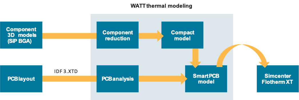
Figure 1: Thales Thermal Analysis Workbench (WATT).
Until now, this effort has been hampered by the inability to incorporate all thermally-relevant details into the detailed model due to the large number of microscopic elements that are present within an electronic component. More than ever, a fine representation of all the details of a small package is today mandatory to avoid an overestimation of the semiconductor temperature.

Figure 2: The realistic modeling of a QFN 16 package reduces the temperature prediction by 20 percent
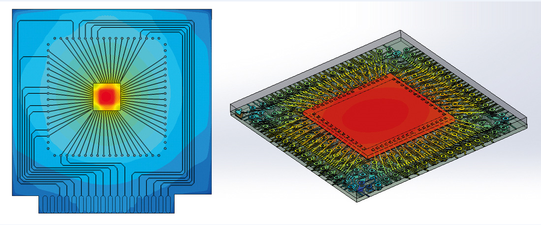
Figure 3. Component on JEDEC 2s2p test board in FloTHERM XT, showing internal detail including bond wires
There has always been a conservative design margin applied at the component level due to the fact that it has either taken too long or simply been impractical to take into account all the geometries inside a component package. For example, the detailed copper traces, copper vias on the substrate as well as the bond wires between the die and the substrate were rarely modeled explicitly, but are known to contribute to the heat spreading. Until now these very small elements were either roughly represented by single parts with averaged thermal properties or simply ignored. Their replacement by single aggregated parts introduces some inaccuracies in the results, while ignoring them leads to a higher calculated temperature and consequently higher margins during the design process.
With FloTHERM XT, the Core Thermal Team has been able to take a major step forward, producing, in just a few hours, results for System-in-Package devices or conventional BGA or LGA packages including all geometric elements inside the package.
For instance, the Thales Core Thermal Team has been able to import the complete geometry of a FpBGA 208 package with all its internal details as well as its supported board test vehicle, then set the general boundary conditions in just a few hours.
The meshing strategy of FloTHERM XT, which is based on the local size of the different parts of the model, requires very few user inputs and allows for the creation of an appropriate and easily solvable 1.9-million-cell mesh in less than three hours of computation on a 12- core Intel Xeon processor. The powerful solver needed less than 4.5 hours to reach full convergence on the same processor using 10 Gb of memory. This short computational time has allowed quick comparisons on the influence of the 25μm (1mil) bond wires on the package’s thermal performance both in natural convection and in forced convection at different velocities.
The numerical results are very close to the measurements already conducted on this component, and are within 1% for the natural convection case, as shown in Table 1.
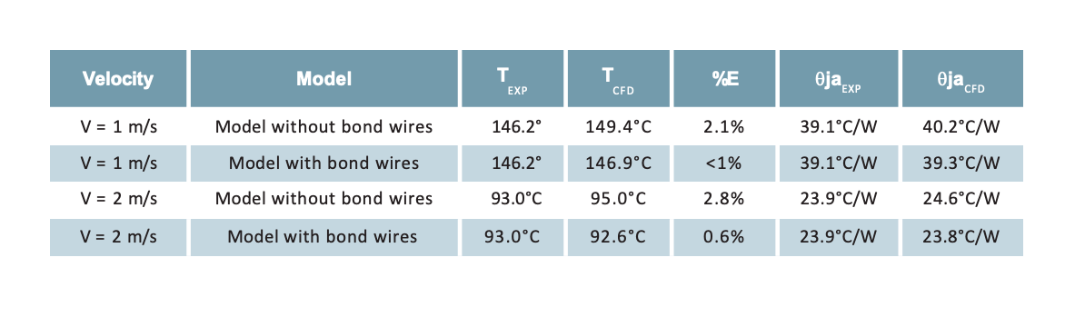

Figure 4: Detail of heat spreading throughout complex copper traces and vias (inset: X-ray showing bond wires).
Increased simulation accuracy is the only way to break the conservative design margins used in the past.
Respecting these former margins would cost a lot more today than in the past due to the increased power density, so it is essential that cooling systems are made as efficient as possible, and for that simulation accuracy at all packaging levels is needed.
Further, a fine representation of FpBGA 208 internal structure permits to better understand the thermal constraints encountered by the PCB interconnect balls, especially at corner locations. Figure 3 highlights a temperature gradient of 48°C for the set of interconnect balls.

Figure 5: Simcenter Flotherm XT is poised to take a major role in Thales’ overall thermal design workflow.
If the modeling of the internal structure of the electronic component is crucial to accurately predict the temperature of its chip(s), the layer layout and copper trace design of the electronic board is now essential to efficiently optimize the way the heat is spread throughout its structure. Even there FloTHERM XT can simulate the small and thin elements that make up its composite structure.
This new approach, afforded by FloTHERM XT, means that the conservative design margins of the past can be reviewed, paving the way to accurately predict the thermal behavior of systems at all packaging levels, and particularly at the component level where the highest temperature gradients are located. This will allow Thales to better integrate cooling systems, even in cases where it was impossible with the old conservative margins. And sometimes it helps to comprehend previously misunderstood multiphysics issues.
“The thermal design of electronic component is under increasing control. With FloTHERM XT we can import the complete geometry of a FpBGA 208 package with all its internal details, test board, setup the boundary conditions and solve it in just a few hours. This will allow Thales to better integrate cooling systems, and comprehend previously misunderstood multiphysics issues.”
Credit: Siemens Digital Industries Software
If you have any inquiry or more information related to Simcenter™ software, please don’t hesitate to reach us by click the below button.