

When we have a relatively small size and simple shape of UUT, with a simple mounting pattern, simple product orientation and low frequency test range, it will not be so tough to design a good vibration test fixture.
But when we start to see one or more of below characteristics, then likely we will find designing vibration test fixture to be very challenging.
Large size UUT
UUT with high mounting point position
UUT with specific angle of mounting orientation
Beyond 500 Hz test frequency
The requirement to test more than one UUT at the same time
The requirement to test more than one UUT at different axis at the same time
Limited fixture weight allowance due to limited force capacity

In this kind of condition, pushing the resonance frequency far beyond the test frequency range may not be easy anymore.
Without tools to predict the resonance frequency, trial and error will be the only way to achieve the objective. And it may take many prototypes to fabricate, weeks to months fabrication period plus testing and validation.
Is it possible to perform simple hand calculation to predict the resonance?
For a simple vibration test fixture: yes, it is. But for relatively complex structure, it will be nearly impossible.
Is it possible to generate our own finite element model (FEM) simulation?
For a simple structure formed by one dimensional trusses element, yes it may be possible. But for complex 3-dimensional element, it may take months to come out with good validation results.
Even though we already have a FEM simulation software that allows us to run many types of simulations, still there are some details that we need to pay attention during the model creation and analysis.
Type of Element
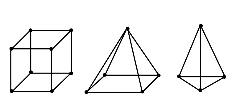
In a case of simple design with low number of elements, using one dimensional or two-dimensional type of element will be preferable, since it may keep the number of nodes low to save the computing resource and computational time needed.
But for complex design, many times using the three-dimensional type of element will be preferable because of some features provided by software manufacturer make it easier to handle 3D element rather than 2D or 1D element.
Having 3D element will lead to more nodes, more DOF, larger matrix and ended up with longer computational time. Even worse, if we can't use hexahedral element type, due to the complex shape of fixture design, then we will need to use tetrahedral element. But since 1st order of tetrahedral element has less accuracy for "bending" case, then we should use 2nd order tetrahedral element type. This means, the number of nodes becomes even larger and the matrix becomes even bigger.
But thanks to the rapid development of high resource computing, nowadays the cost high performance PC is much more affordable than before.
From another point of view, saving on modelling time has also become important consideration, other than saving of analysis time.
Size of Element
Size of element is also playing important part to the accuracy of the FEM simulation. Generally, smaller size element will provide more accuracy than bigger size of element. But we also know that smaller size element leads to higher number of nodes, which end up with longer computational time. In some case, we can't avoid using small size element in the area which has complex shape, especially at the stress concentration area, which likely will have more strain or deformation. Having too large element size in this kind of area may provide unnecessary extra stiffness, which may reduce the accuracy of the result. In some cases, the FEM engineer may need to perform convergence test, to find the optimum size of element.
Type of Connection between Element
Ideally, we will prefer to have one piece of aluminum or magnesium as our vibration test fixture. But in most of the cases, this is not applicable. Producing one-piece of aluminum or magnesium as vibration test fixture through die casting and/or machining process will be too expensive.
To use welded multiple plates may become an option, but aluminum welding is not commonly available in some region. Other than that, welding is also not an easy process to perform due to the thermal deformation during and after the process.
From the FEM perspective, welding connection is not impossible to model.
We may just want to pay attention on the property of the welded area, which generally has higher stiffness compare to the regular material.
Next, the other practical option will be using multiple plates with screw connections. This one is much easier to fabricate and may be considered as the most practical option. Some software manufacturers even provide special feature to model screw connection.
Type of Simulation
Most type of simulations provided by software manufacturer can be classified into two types, static and dynamic simulation.
Each static and dynamic simulation can be classified again into linear and non-linear simulation.
For designing vibration test fixture, we should be able to use dynamic linear type of simulation.
To use dynamic non-linear simulation type for designing vibration test fixture may be considered an overkill.
Most of FEM software may offer below type of simulations:
Normal Mode
Frequency Domain Response
Time Domain Response
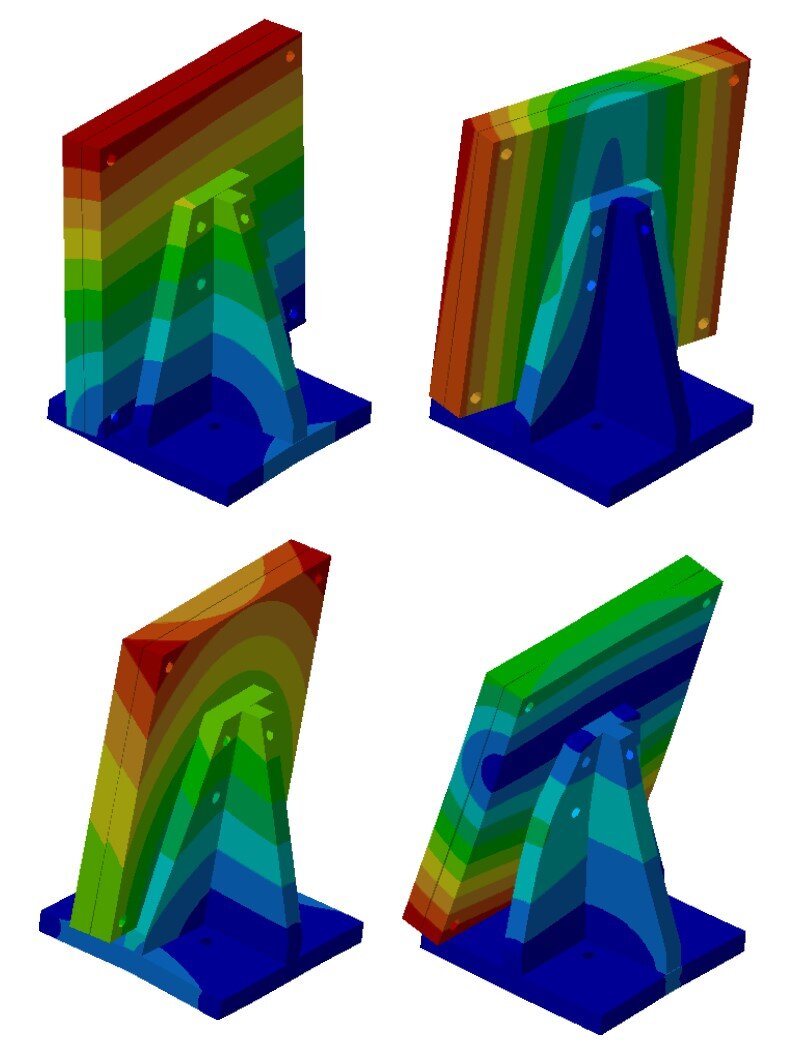
For designing vibration test fixture, performing normal mode simulation should be good enough, since we will be able to obtain the resonance frequencies and the mode shape at each resonance.
By having the mode shape, we should be able to understand better on how to increase the stiffness or reduce the mass which are not contributing to the structure stiffness. Unless it is not possible to push the resonance out from the test frequency range, then we may want to use the Frequency Response Simulation. Running frequency response simulation will be much more challenging compare to normal mode since the accuracy of the result will not be depending only on mass and stiffness, but also the damping properties that we put into the simulation.
Non-linearity
Even though we are using the dynamic linear type of simulation, our vibration test fixture will definitely have non-linearities.
The source of non-linearity may come from the material itself, but also due to non-linear boundary condition as results of non-linear surface contact between metal plates.
This non-linear surface contact may add in some stiffness to the structure. This non-linearity may also be influenced by the mode shape at each resonance frequency.